Add a Standalone Firewall Threat Defense

Standalone logical devices work either alone or in a High Availability pair. On the Firepower 9300 with multiple security modules, you can deploy either a cluster or standalone devices. The cluster must use all modules, so you cannot mix and match a 2-module cluster plus a single standalone device, for example.

Before you begin

  • Download the application image you want to use for the logical device from Cisco.com, and then upload that image to the Firepower 4100/9300 chassis.

    Note

    For the Firepower 9300, you can install different application types (ASA and Firewall Threat Defense) on separate modules in the chassis. You can also run different versions of an application instance type on separate modules.

  • Configure a management interface to use with the logical device. The management interface is required. Note that this management interface is not the same as the chassis management port that is used only for chassis management (and that appears at the top of the Interfaces tab as MGMT).

  • You can later enable management from a data interface; but you must assign a Management interface to the logical device even if you don't intend to use it after you enable data management. See the configure network management-data-interface command in the FTD command reference for more information.

  • You must also configure at least one Data type interface. Optionally, you can also create a firepower-eventing interface to carry all event traffic (such as web events). See Interface Types for more information.

  • Gather the following information:

    • Interface IDs for this device

    • Management interface IP address and network mask

    • Gateway IP address

    • Firewall Management Center IP address and/or NAT ID of your choosing

    • DNS server IP address

    • Firewall Threat Defense hostname and domain name

Procedure


Step 1

Choose Logical Devices.

Step 2

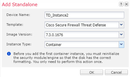
Click Add > Standalone, and set the following parameters:

  1. Provide a Device Name.

    This name is used by the chassis supervisor to configure management settings and to assign interfaces; it is not the device name used in the application configuration.

    Note

    You cannot change this name after you add the logical device.

  2. For the Template, choose Cisco Firepower Threat Defense.

  3. Choose the Image Version.

  4. Click OK.

    You see the Provisioning - device name window.

Step 3

Expand the Data Ports area, and click each interface that you want to assign to the device.

You can only assign data interfaces that you previously enabled on the Interfaces page. You will later enable and configure these interfaces in Firewall Management Center, including setting the IP addresses.

Hardware Bypass-capable ports are shown with the following icon: . For certain interface modules, you can enable the Hardware Bypass feature for Inline Set interfaces only (see the Firewall Management Center configuration guide). Hardware Bypass ensures that traffic continues to flow between an inline interface pair during a power outage. This feature can be used to maintain network connectivity in the case of software or hardware failures. If you do not assign both interfaces in a Hardware Bypass pair, you see a warning message to make sure your assignment is intentional. You do not need to use the Hardware Bypass feature, so you can assign single interfaces if you prefer.

Step 4

Click the device icon in the center of the screen.

A dialog box appears where you can configure initial bootstrap settings. These settings are meant for initial deployment only, or for disaster recovery. For normal operation, you can later change most values in the application CLI configuration.

Step 5

On the General Information page, complete the following:

  1. (For the Firepower 9300) Under Security Module Selection click the security module that you want to use for this logical device.

  2. Choose the Management Interface.

    This interface is used to manage the logical device. This interface is separate from the chassis management port.

  3. Choose the management interface Address Type: IPv4 only, IPv6 only, or IPv4 and IPv6.

  4. Configure the Management IP address.

    Set a unique IP address for this interface.

  5. Enter a Network Mask or Prefix Length.

  6. Enter a Network Gateway address.

Step 6

On the Settings tab, complete the following:
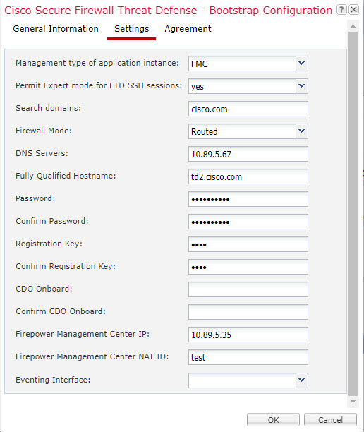
  1. For a native instance, in the Management type of application instance drop-down list, choose FMC.

    Native instances also support Firewall Device Manager as a manager. After you deploy the logical device, you cannot change the manager type.

  2. Enter the Firepower Management Center IP of the managing Firewall Management Center. If you do not know the Firewall Management Center IP address, leave this field blank and enter a passphrase in the Firepower Management Center NAT ID field.

  3. Enter the Search Domains as a comma-separated list.

  4. Choose the Firewall Mode: Transparent or Routed.

    In routed mode, the Firewall Threat Defense is considered to be a router hop in the network. Each interface that you want to route between is on a different subnet. A transparent firewall, on the other hand, is a Layer 2 firewall that acts like a “bump in the wire,” or a “stealth firewall,” and is not seen as a router hop to connected devices.

    The firewall mode is only set at initial deployment. If you re-apply the bootstrap settings, this setting is not used.

  5. Enter the DNS Servers as a comma-separated list.

    The Firewall Threat Defense uses DNS if you specify a hostname for the Firewall Management Center, for example.

  6. Enter the Fully Qualified Hostname for the Firewall Threat Defense.

  7. Enter a Registration Key to be shared between the Firewall Management Center and the device during registration.

    You can choose any text string for this key between 1 and 37 characters; you will enter the same key on the Firewall Management Center when you add the Firewall Threat Defense.

  8. Enter a Password for the Firewall Threat Defense admin user for CLI access.

  9. Choose the Eventing Interface on which events should be sent. If not specified, the management interface will be used.

    This interface must be defined as a Firepower-eventing interface.

  10. For a container instance, set the Hardware Crypto as Enabled or Disabled.

    This setting enables TLS crypto acceleration in hardware, and improves performance for certain types of traffic. This feature is enabled by default. You can enable TLS crypto acceleration for up to 16 instances per security module. This feature is always enabled for native instances. To view the percentage of hardware crypto resources allocated to this instance, enter the show hw-crypto command.

Step 7

On the Agreement tab, read and accept the end user license agreement (EULA).

Step 8

Click OK to close the configuration dialog box.

Step 9

Click Save.

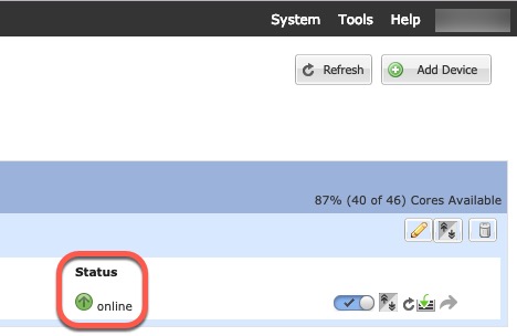
The chassis deploys the logical device by downloading the specified software version and pushing the bootstrap configuration and management interface settings to the application instance. Check the Logical Devices page for the status of the new logical device. When the logical device shows its Status as online, you can start configuring the security policy in the application.
Step 10

See the Firewall Management Center configuration guide to add the Firewall Threat Defense as a managed device and start configuring your security policy.