Form a cluster from one or more devices in the Cloud-Delivered
Firewall Management Center.
Procedure
Step 1
Choose Devices > Device Management, and then choose Add > Cluster.
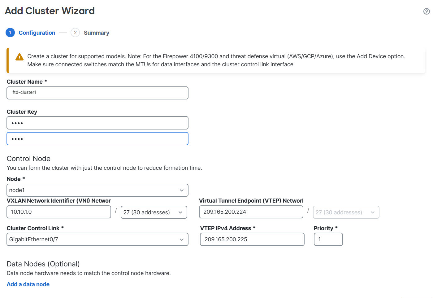
The Add Cluster Wizard appears.
Add Cluster Wizard
Step 2
Specify a
Cluster Name
and an authentication
Cluster Key
for control traffic.
Cluster Name—An ASCII string of 1 to 38 characters. The cluster name can contain only letters, digits, underscores (_), and hyphens (-).
Cluster Key—An ASCII string of 1 to 63 characters. The cluster key cannot be a single digit and must not contain spaces. The Cluster Key value is used to generate the encryption key. This encryption does not affect datapath traffic, including connection state update and forwarded packets, which are always sent in clear text.
Step 3
For the Control Node, configure these parameters:
Node—Choose the device that you want to be the control node initially. When the Cloud-Delivered
Firewall Management Center forms the cluster, it will add this node to the cluster first so it will be the control node.
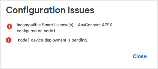
Note
If you see an Error () icon next to the node name, click the icon to view configuration issues. You must cancel cluster formation, resolve the issues, and then return to cluster formation. For example:
Configuration Issues
To resolve the above issues, remove the unsupported VPN license and deploy pending configuration changes to the device.
Cluster Control Link Network—Specify an IPv4 subnet; IPv6 is not supported for this interface. Specify a 24, 25, 26, or 27 subnet.
Cluster Control Link—Choose the physical interface or EtherChannel you want to use for the cluster control link.
Note
The MTU of the cluster control link interface is automatically set to 100 bytes more than the highest data interface MTU; by default, the MTU is 1600 bytes. We do not recommend setting the cluster control link MTU between 2561 and 8362; due to block pool handling, this MTU size is not optimal for system operation. If the MTU is set in this range when you add the cluster, we recommend increasing the MTU above 8362. Choose Devices > Device Management and then click Interfaces.
Make sure you configure switches connected to the cluster control link to the correct (higher) MTU; otherwise, cluster formation can fail.
Cluster Control Link IPv4 Address—This field will be auto-populated with the first address on the cluster control link network. You can edit the host address if desired.
Priority—Set the priority of this node for control node elections. The priority is between 1 and 100, where 1 is the highest priority. Even if you set the priority to be lower than other nodes, this node will still be the control node when the cluster is first formed.
Site ID—(FlexConfig feature) Enter the site ID for this node between 1 and 8. A value of 0 disables inter-site clustering. Additional inter-site cluster customizations to enhance redundancy and stability, such as director localization, site redundancy, and cluster flow mobility, are only configurable using the FlexConfig feature.
Step 4
For the Cluster Mode, choose Spanned EtherChannel Mode or Individual Interface Mode .
Step 5
For Data Nodes (Optional), click Add a data node to add a node to the cluster.
You can form the cluster with only the control node for faster cluster formation, or you can add all nodes now. Set the following for each data node:
Node—Choose the device that you want to add.
Note
If you see an Error () icon next to the node name, click the icon to view configuration issues. You must cancel cluster formation, resolve the issues, and then return to cluster formation.
Cluster Control Link IPv4 Address—This field will be auto-populated with the next address on the cluster control link network. You can edit the host address if desired.
Priority—Set the priority of this node for control node elections. The priority is between 1 and 100, where 1 is the highest priority.
Site ID—(FlexConfig feature) Enter the site ID for this node between 1 and 8. A value of 0 disables inter-site clustering. Additional inter-site cluster customizations to enhance redundancy and stability, such as director localization, site redundancy, and cluster flow mobility, are only configurable using the FlexConfig feature.
Step 6
Click Continue. Review the Summary, and then click Save.
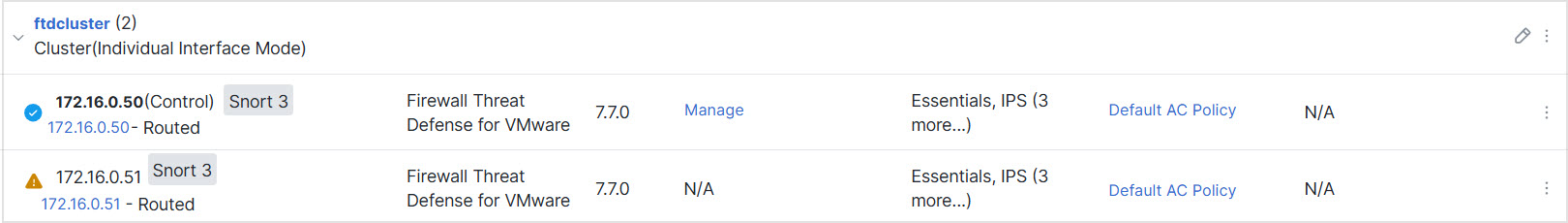
The cluster name shows on the Devices > Device Management page; expand the cluster to see the cluster nodes.
Cluster Management
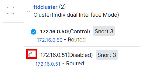
A node that is currently registering shows the loading icon.
Node Registration
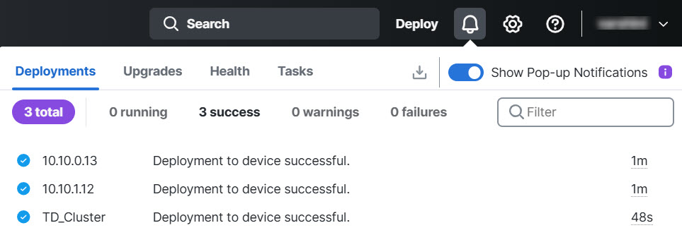
You can monitor cluster node registration by clicking the Notifications icon and choosing Tasks. The Cloud-Delivered
Firewall Management Center updates the Cluster Registration task as each node registers.
Step 7
Configure device-specific settings by clicking the
Edit ()
for the cluster.
Most configuration can be applied to the cluster as a whole, and not nodes in the cluster. For example, you can change the display name per node, but you can only configure interfaces for the whole cluster.
Step 8
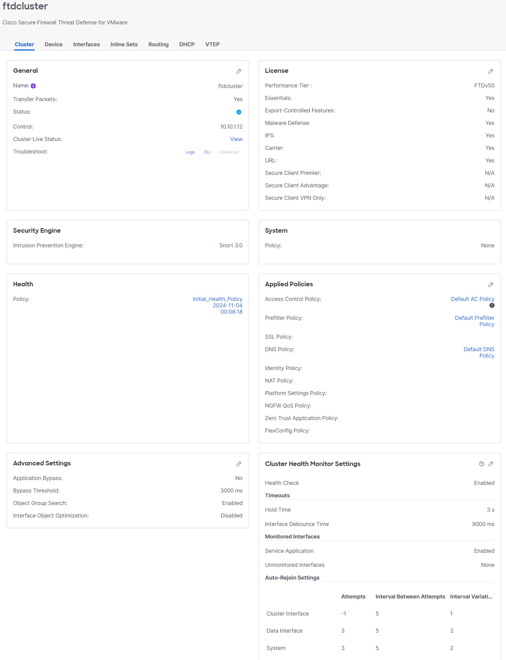
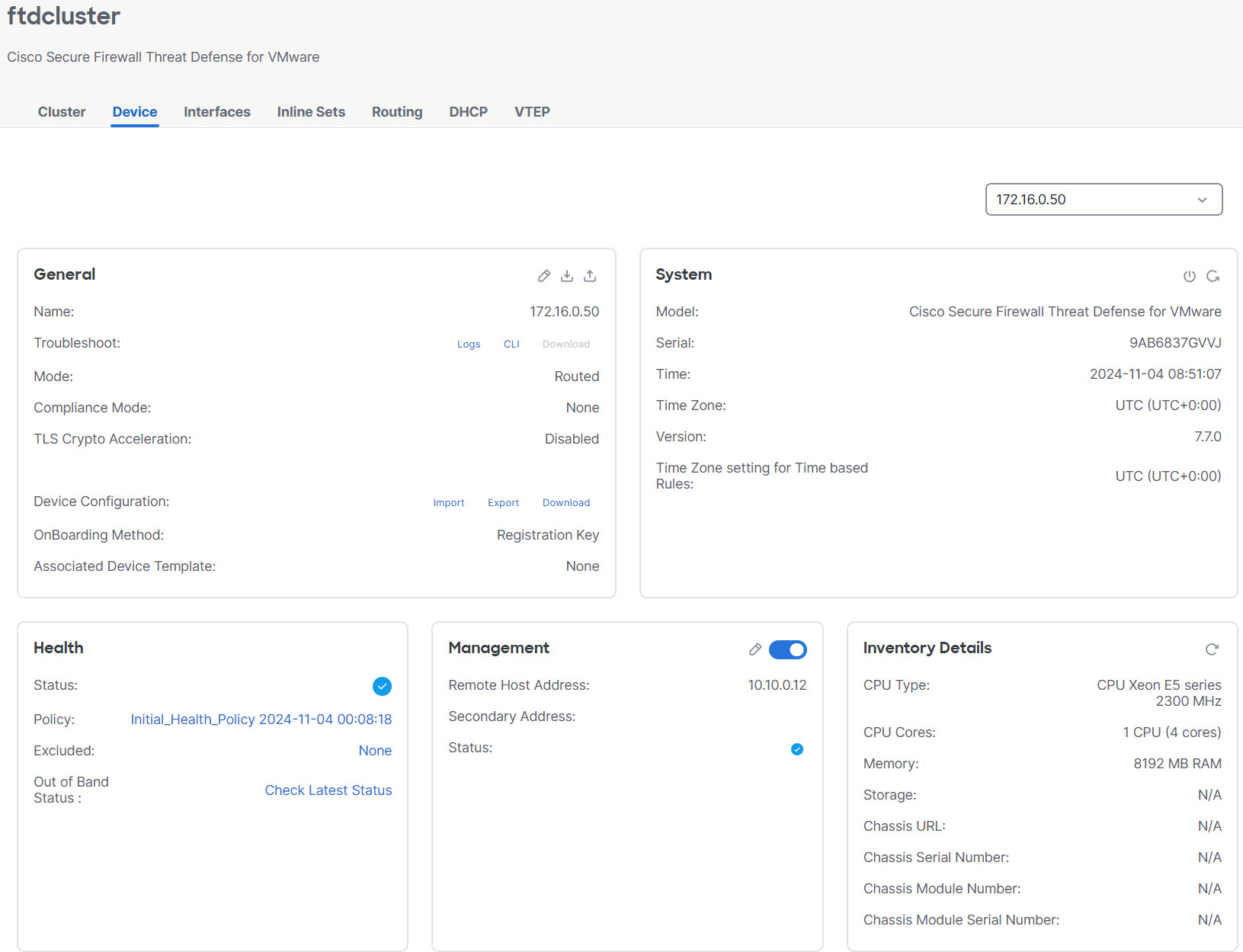
On the Devices > Device Management and then choose Add, Cluster screen, you see General and other settings for the cluster.
Cluster Settings
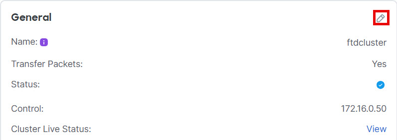
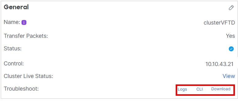
See these cluster-specific items in the General area:
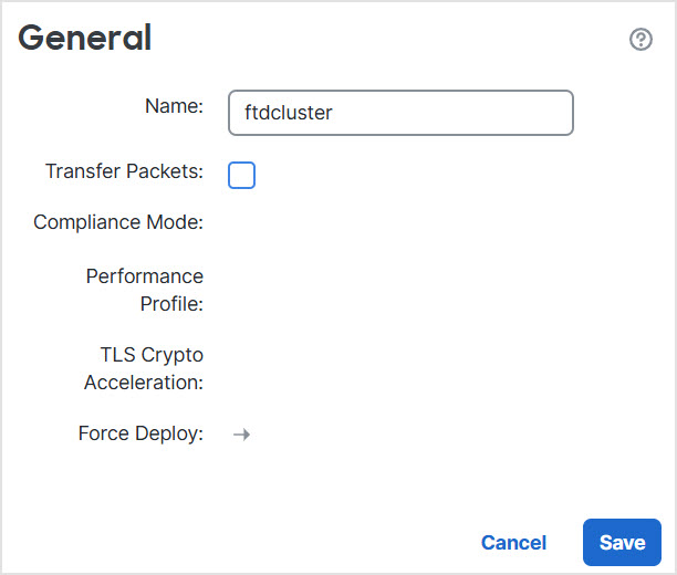
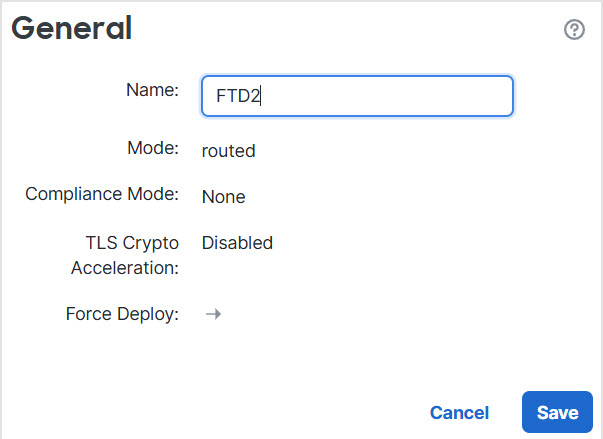
General > Name—Change the cluster display name by clicking the Edit ().
Then set the Name field.
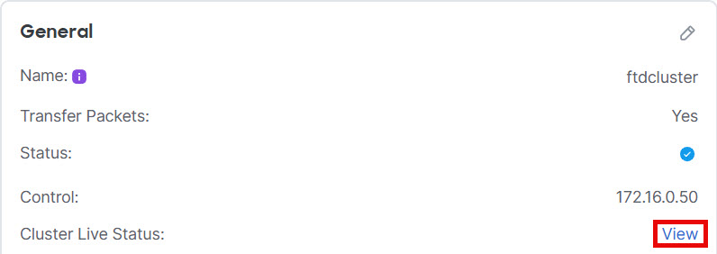
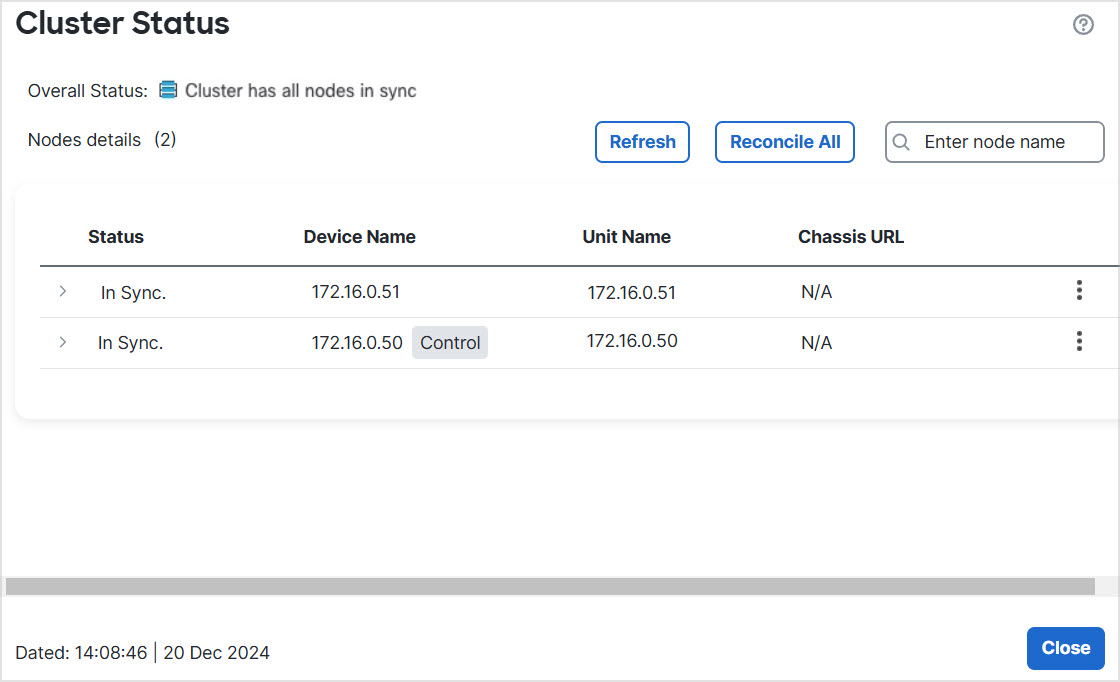
General > Cluster Live Status—Click the View link to open the Cluster Status dialog box.
The Cluster Status dialog box also lets you retry data unit registration by clicking Reconcile All.
General > Troubleshoot—You can generate and download troubleshooting logs, and you can view cluster CLIs. Refer Troubleshoot the cluster .
Troubleshoot
Step 9
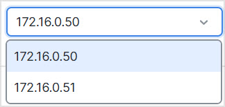
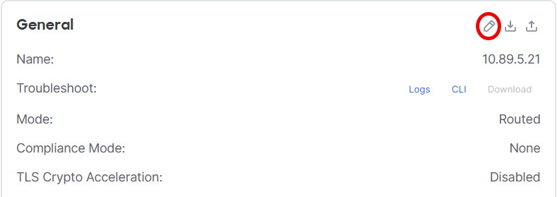
On the Devices > Device Management and then choose Add, Device, you can choose each member in the cluster from the top right drop-down menu and configure these settings.
Device SettingsChoose Node
General > Name—Change the cluster member display name by clicking the Edit () .
Then set the Name field.
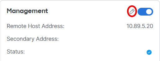
Management > Host —If you change the management IP address in the device configuration, you must match the new address in the Cloud-Delivered
Firewall Management Center so that it can reach the device on the network. First disable the connection, edit the Host address in the Management area, then re-enable the connection.