Exempt Site-to-Site VPN Traffic from NAT
When you have a site-to-site VPN connection defined on an interface, and you also have NAT rules for that interface, you can optionally exempt the traffic on the VPN from the NAT rules. You might want to do this if the remote end of the VPN connection can handle your internal addresses.
When you create the VPN connection, you can select the NAT Exempt option to create the rules automatically. However, this works only if your local protected network is connected through a single routed interface (not a bridge group member). If instead, the local networks in the connection reside behind two or more routed interfaces or one or more bridge group members, you need to configure the NAT exempt rules manually.
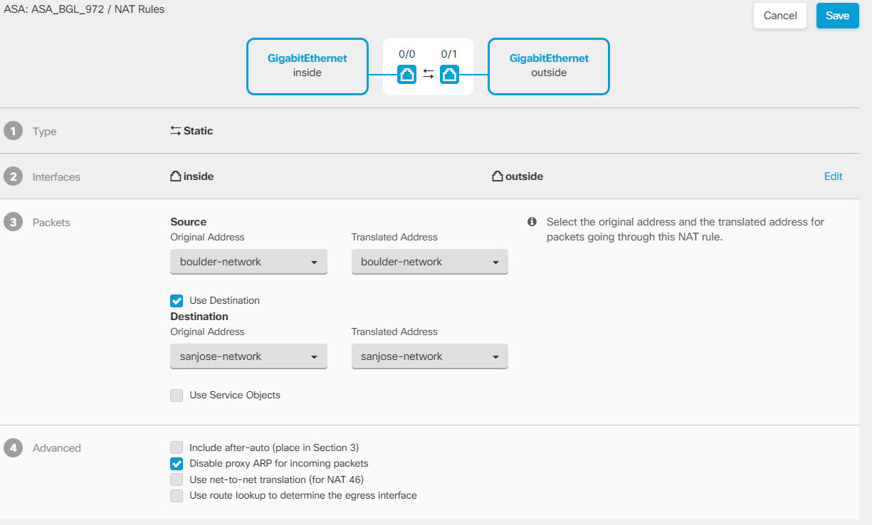
To exempt VPN traffic from NAT rules, you create an identity manual NAT rule for the local traffic when the destination is the remote network. Then, apply NAT to the traffic when the destination is anything else (for example, the Internet). If you have more than one interface for the local network, create rules for each interface. Also, consider the following suggestions:
-
If there is more than one local network in the connection, create a network object group to hold the objects that define the networks.
-
If you are including both IPv4 and IPv6 networks in the VPN, create separate identity NAT rules for each.
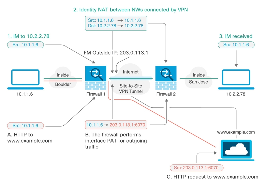
Consider the following example, which shows a site-to-site tunnel connecting the Boulder and San Jose offices. For traffic that you want to go to the Internet (for example from 10.1.1.6 in Boulder to www.example.com), you need a public IP address provided by NAT to access the Internet. The below example uses interface Port Address Translation (PAT) rules. However, for traffic that you want to go over the VPN tunnel (for example from 10.1.1.6 in Boulder to 10.2.2.78 in San Jose), you do not want to perform NAT; you need to exempt that traffic by creating an identity NAT rule. Identity NAT translates an address to the same address.

The following example explains the configuration for Firewall1 (Boulder). The example assumes that the inside interface is a bridge group, so you need to write the rules for each member interface. The process is the same if you have a single or multiple routed inside interfaces.
Note | This example assumes IPv4 only. If the VPN also includes IPv6 networks, create parallel rules for IPv6. Note that you cannot implement IPv6 interface PAT, so you need to create a host object with a unique IPv6 address to use for PAT. |
Procedure
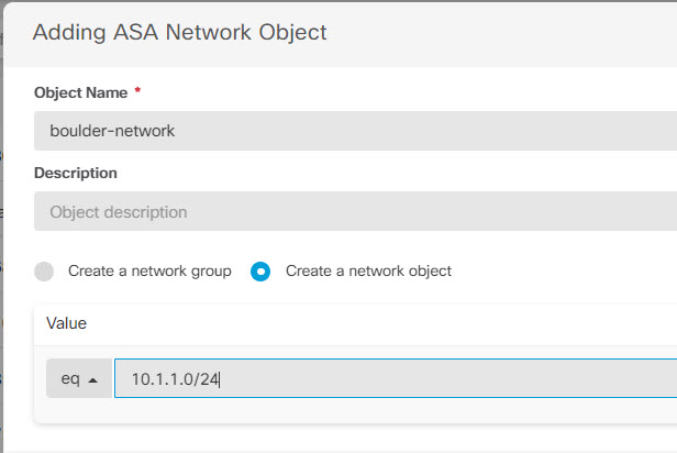
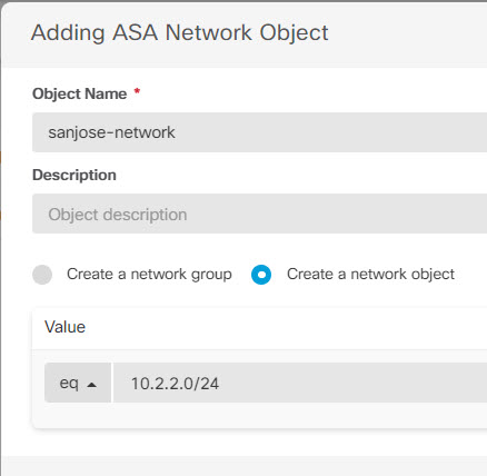
Step 1 | Create objects to define the various networks.
|
Step 2 | Configure manual identity NAT for the Boulder network when going over the VPN to San Jose on Firewall1 (Boulder).
|
Step 3 | Configure manual dynamic interface PAT when going to the Internet for the inside Boulder network on Firewall1 (Boulder). Note: There might already be dynamic interface PAT rules for the inside interfaces, covering any IPv4 traffic, as these are created by default during initial configuration. However, the configuration is shown here for completeness. Before completing these steps, check whether a rule already exists that covers the inside interface and network, and skip this step if it does.
|
Step 4 | Deploy configuration changes to Security Cloud Control. For more information, see Deploy Configuration Changes Made Using the Security Cloud Control GUI. |
Step 5 | If you are also managing Firewall2 (San Jose), you can configure similar rules for that device.
|
 to create an object.

 .
.
