Sample topology
The sample topology provided below
-
depicts both inbound and outbound traffic flow through security appliances,
-
includes three Threat Defense Virtual instances in a cluster connected to a GWLB, and
-
uses a Management Center Virtual instance to manage the cluster.
Traffic flow
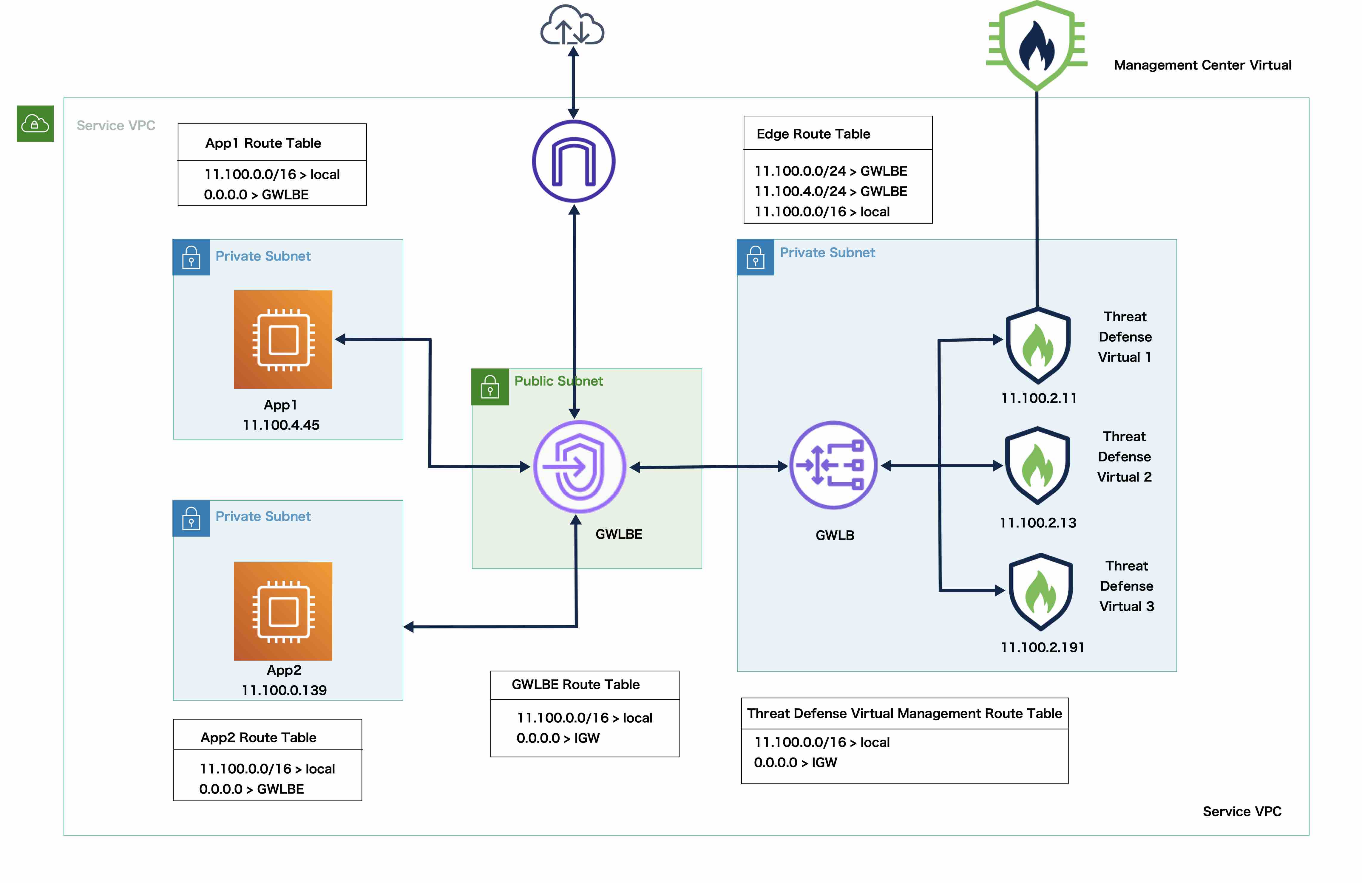
Inbound traffic from the internet goes to the GWLB endpoint which then transmits the traffic to the GWLB. Traffic is then forwarded to the Threat Defense Virtual cluster. After the traffic has been inspected by a Threat Defense Virtual instance in the cluster, it is forwarded to the application VM, App1 /App2.
Outbound traffic from App1/App2 is transmitted to the GWLB endpoint which then sends it out to the internet.