Sample Topology of GCP Clustering Autoscale Solution
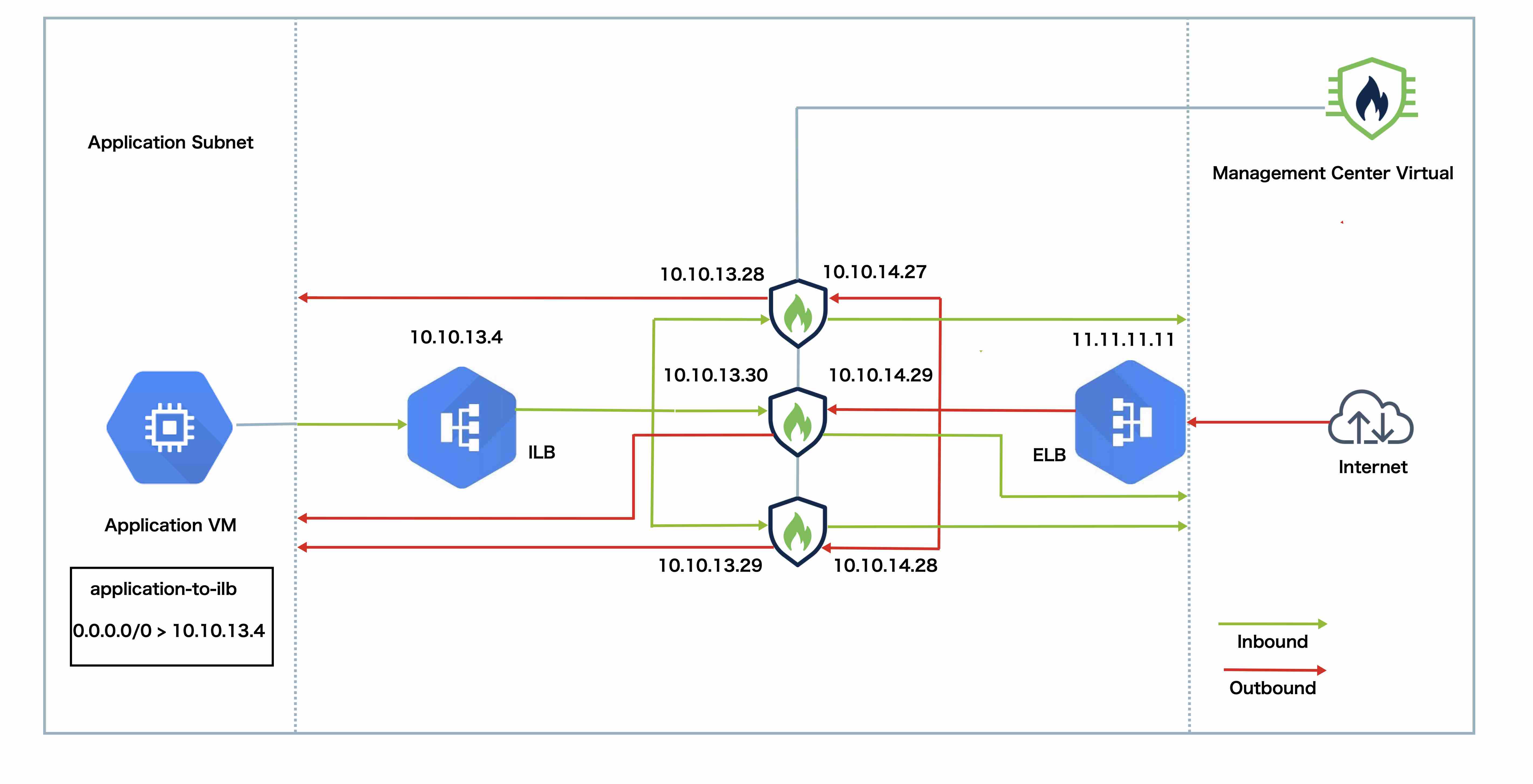
The topology shows both inbound and outbound traffic flow.
-
The Threat Defense Virtual cluster is placed between the internal and external load balancers. A Management Center Virtual instance is used to manage the cluster.
-
Inbound traffic from the internet goes to the external load balancer, which then transmits the traffic to the Threat Defense Virtual cluster.
-
The Threat Defense Virtual instance in the cluster inspects the traffic, and after inspection, forwards the traffic to the application VM.
-
Outbound traffic from the application VM goes to the internal load balancer. The load balancer forwards this traffic to the Threat Defense Virtual cluster, which sends it to the internet.