How to Allow RA VPN Access to Internal Networks in Virtual Routing

On virtual routing-enabled devices, RA VPN is supported only on global virtual router interfaces. This example provides the procedure that allows your Secure Client user to connect to user-defined virtual router networks.

In the following example, the RA VPN (Secure Client) user connects to the outside interface of threat defense at 172.16.3.1, and is given an IP address within the pool of 192.168.80.0/24. The user can access the inside network of only the global virtual router. To allow traffic flow through the network of the user-defined virtual router VR1, namely 192.168.1.0/24, leak the route by configuring the static routes on global and VR1.

Virtual routers and RA VPN network diagram.

Before you begin

This example assumes that you have already configured the RA VPN, defined the virtual routers, and configured and assigned the interfaces to the appropriate virtual routers.

Procedure


Step 1

Configure route leak from Global virtual router to the user-defined VR1:

  1. Choose Devices > Device Management, and edit the threat defense device.

  2. Click Routing. By default, the Global routing properties page appears.

  3. Click Static Route.

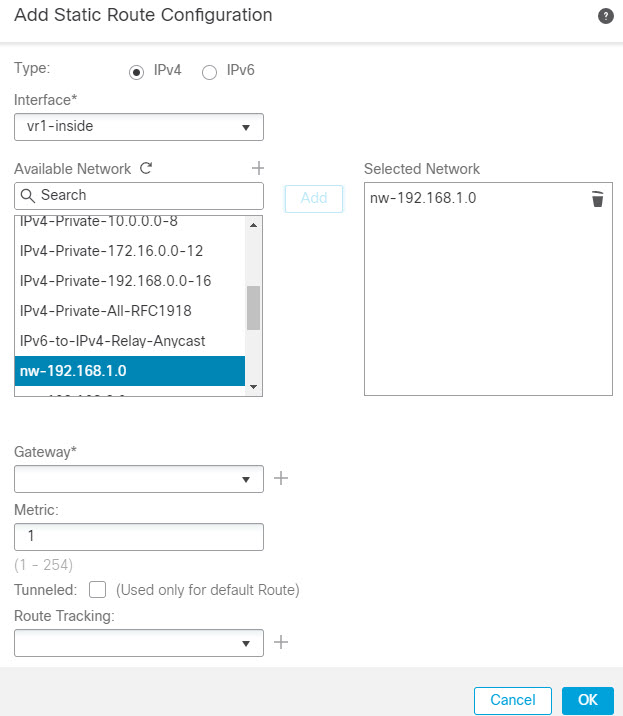
  4. Click Add Route. In Add Static Route Configuration, specify the following:

    • Interface—Select the VR1 inside interface.

    • Network—Select the VR1 virtual router network object. You can create one using the Add Object option.

    • Gateway—Leave it blank. When leaking a route into another virtual router, does not select the gateway.

    The route leak allows Secure Client assigned IP addresses in the VPN pool to access the 192.168.1.0/24 network in the VR1 virtual router.

  5. Click Ok.

Step 2

Configure the route leak from VR1 to the Global virtual router:

  1. Choose Devices > Device Management, and edit the threat defense device.

  2. Click Routing and from the drop-down, select VR1.

  3. Click Static Route.

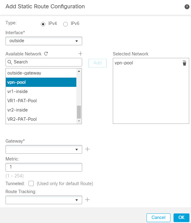
  4. Click Add Route. In Add Static Route Configuration, specify the following:

    • Interface—Select the outside interface of the global router.

    • Network—Select the global virtual router network object.

    • Gateway—Leave it blank. When leaking a route into another virtual router, does not select the gateway.

    The configured static route allows endpoints on the 192.168.1.0/24 network (VR1) to initiate connections to Secure Client assigned IP addresses in the VPN pool.

  5. Click Ok.


What to do next

If RA VPN address pool and the IP addresses in the user-defined virtual router overlap, you must also use static NAT rules on the IP addresses to enable proper routing. Alternatively, you can change your RA VPN address pool so that there is no overlap.