Add More Cluster Nodes
Add or replace the Firewall Threat Defense cluster node in an existing cluster.
Note | The FXOS steps in this procedure only apply to adding a new chassis; if you are adding a new module to a Firepower 9300 where clustering is already enabled, the module will be added automatically. However, you must still add the new module to the Firewall Management Center; skip to the Firewall Management Center steps. |
Before you begin
-
In the case of a replacement, you must delete the old cluster node from the Firewall Management Center. When you replace it with a new node, it is considered to be a new device on the Firewall Management Center.
-
The interface configuration must be the same on the new chassis. You can export and import FXOS chassis configuration to make this process easier.
Procedure
Step 1 | If you previously upgraded the Firewall Threat Defense image using the Firewall Management Center, perform the following steps on each chassis in the cluster. When you upgraded from the Firewall Management Center, the startup version in the FXOS configuration was not updated, and the standalone package was not installed on the chassis. Both of these items need to be set manually so the new node can join the cluster using the correct image version.
| ||
Step 2 | On an existing cluster chassis Firewall Chassis Manager, click Logical Devices. | ||
Step 3 | Click the Show Configuration icon at the top right; copy the displayed cluster configuration. | ||
Step 4 | Connect to the Firewall Chassis Manager on the new chassis, and click . | ||
Step 5 | For the Device Name, provide a name for the logical device. | ||
Step 6 | Click OK. | ||
Step 7 | In the Copy Cluster Details box, paste in the cluster configuration from the first chassis, and click OK. | ||
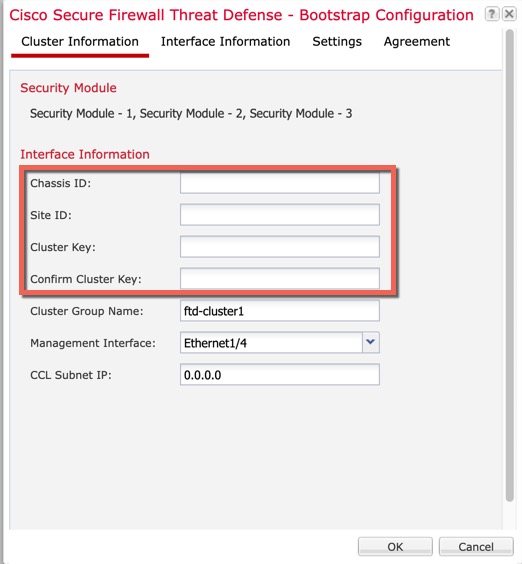
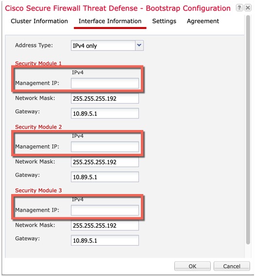
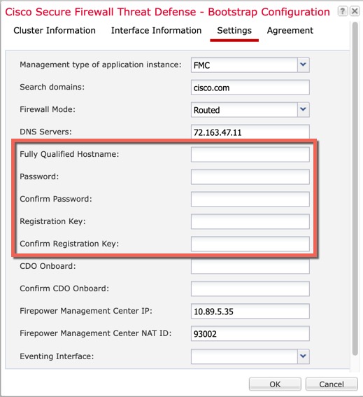
Step 8 | Click the device icon in the center of the screen. The cluster information is partly pre-filled, but you must fill in the following settings: 


Click OK. | ||
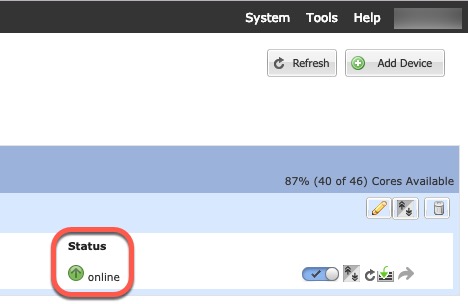
Step 9 | Click Save. The chassis deploys the logical device by downloading the specified software version and pushing the bootstrap configuration and management interface settings to the application instance. Check the Logical Devices page for each cluster member for the status of the new logical device. When the logical device for each cluster member shows its Status as online, you can start configuring the cluster in the application. You may see the "Security module not responding" status as part of the process; this status is normal and is temporary.  |
 )
)