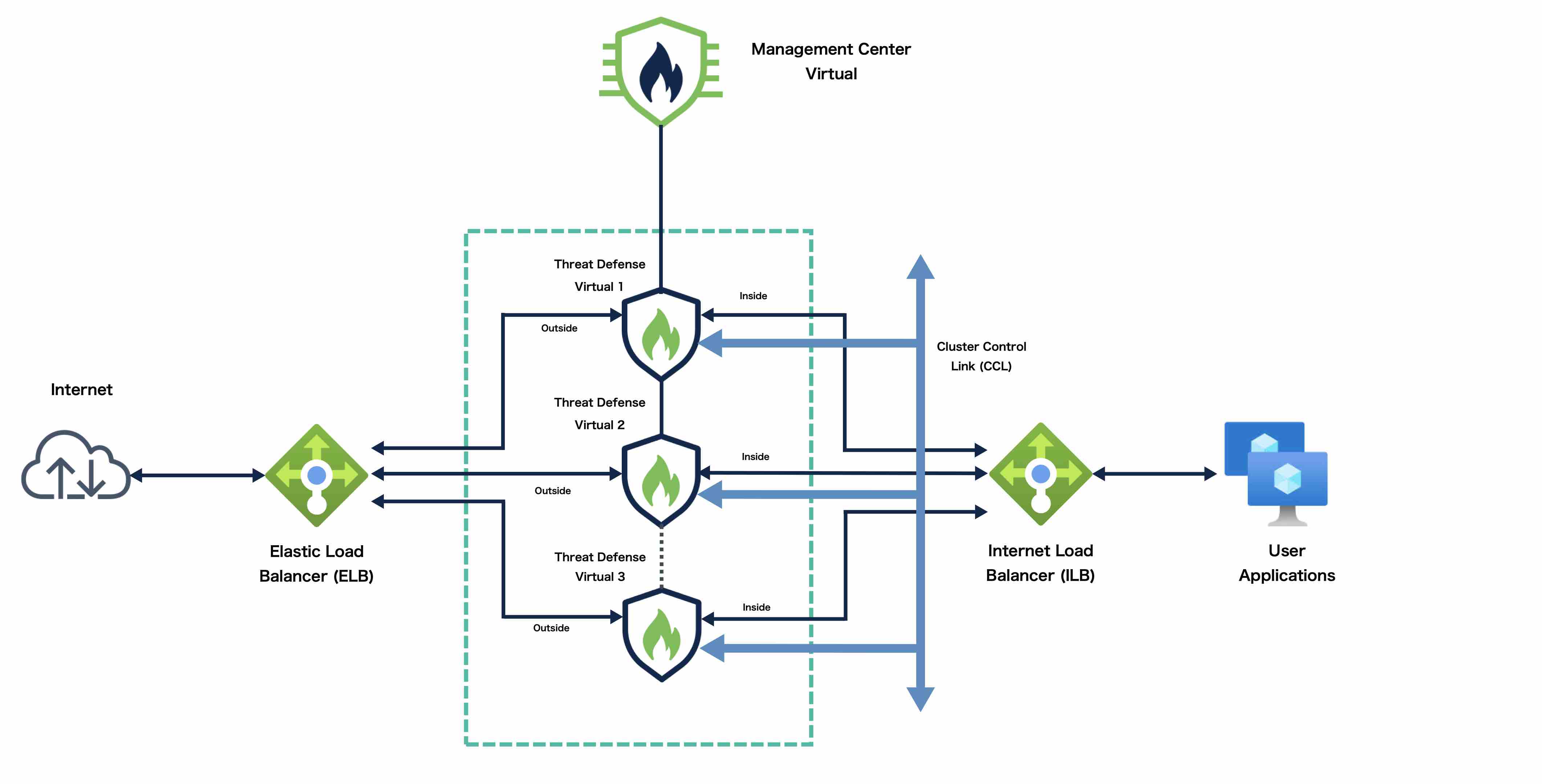
Sample topology for NLB-based cluster deployment
The sample topology provided here
-
places the Threat Defense Virtual cluster between internal and external load balancers,
-
uses a Management Center Virtual instance to manage the cluster, and
-
depicts both inbound and outbound traffic flow patterns.
Traffic flow patterns
This topology shows how traffic moves through the network components:
Inbound traffic: Traffic from the internet goes to the external load balancer, which transmits the traffic to the Threat Defense Virtual cluster. After the traffic has been inspected by a Threat Defense Virtual instance in the cluster, it is forwarded to the application virtual machine (VM).
Outbound traffic: Traffic from the application VM is transmitted to the internal load balancer. Traffic is then forwarded to the Threat Defense Virtual cluster and then sent out to the internet.